How Surveyors Verify Modular Foundation Setout Accuracy
A modular structure can arrive on schedule and still face costly delays if its bearing points miss the foundation by a small amount. Modular foundation setout gives the installation crew a reliable map for placing each section where the approved plans require.
For elevated coastal homes, the stakes are higher. Columns, piers, grade beams, and connection points must line up before a crane ever lifts a module. Survey verification turns dimensions on paper into fixed points on the site.
The work starts with approved drawings, a dependable benchmark, and a careful look at the actual ground conditions.
How Surveyors Verify Modular Foundation Setout Accuracy
Surveyors verify a modular foundation setout by establishing horizontal position, elevation, orientation, and physical bearing locations. They compare field measurements against the approved site plan, foundation plan, and structural drawings.
The goal is not merely to mark corners. The surveyor must confirm that the completed concrete structure matches the footprint and support pattern required for the modules above.
Plans provide the field reference
Before setting layout points, the surveyor reviews the drawing set for dimensions, grid lines, property setbacks, finished-floor elevation, and support schedules. Foundation drawings may call out column centerlines, pier sizes, beam locations, anchor rods, or embedded connection hardware.
A surveyor also checks whether dimensions run from property lines, building grid lines, centerlines, or outside faces of concrete. Confusing one reference point with another can shift every support in the same direction.
On a coastal project, flood requirements often set the finished-floor elevation. That elevation must agree with the approved plans and local permitting documents. A correct footprint at the wrong height can still stop the installation.
Control points keep layout consistent
Survey crews establish control points outside the excavation and concrete work area. These points give the team a stable reference after grading, formwork, or equipment traffic removes temporary stakes.
Control may include:
- A known benchmark for elevation work.
- Offset stakes that preserve building lines outside the foundation footprint.
- Instrument control points for total station setup.
- Reference marks on stable objects when site conditions allow.
Crews should protect those points and identify them clearly. If a dozer, delivery truck, or concrete pump destroys the only reference stake, the surveyor may need to re-establish control before work continues.
Establishing the Building Line and Elevation
A foundation can look square to the eye and still fall outside the approved layout. Survey instruments check angles and distances that tape measures alone can miss, especially across a large elevated structure.
The surveyor first establishes the building's orientation. Then the crew transfers that geometry to column locations, grade beams, piers, and other support elements.
Centerlines matter more than concrete edges
Most structural drawings locate supports by centerline. For example, a concrete column may need to sit at the intersection of Grid A and Grid 3. Its outside edges are secondary because the module's load path lands on the center of the designed support.
Surveyors commonly set hubs, nails, laths, or paint marks for centerlines before excavation. After forms go in, they recheck the form location against those references. This step catches a form that shifted while crews braced it or placed reinforcing steel.
For an elevated concrete structure, the surveyor may also mark beam centerlines and column offsets. Those marks help the concrete crew maintain the designed spacing where multiple supports carry a modular section.
Elevation verification happens at several stages
Vertical accuracy requires more than one reading. The crew checks existing grade before excavation, bottom-of-footing elevation before concrete placement, and top-of-concrete elevation after finishing.
A surveyor uses a level or total station to compare these readings with the project benchmark. The approved plans determine the target elevation and acceptable tolerances.
A concrete surface can be level yet still be wrong if the entire foundation sits above or below the required datum.
Elevated homes often include columns or piers with caps at a common bearing elevation. One cap that finishes high can prevent a module from seating properly. One that finishes low may create an unsupported gap or require an engineered correction.
Verifying Elevated Coastal Foundation Supports
Coastal sites add wind exposure, flood design elevations, drainage features, and restricted access. These conditions make precise support placement especially important.
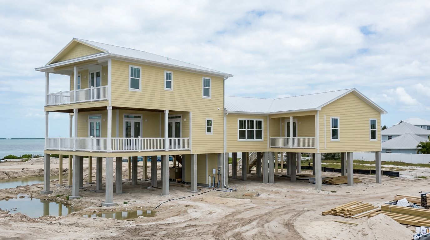
The foundation may include reinforced concrete columns, pile caps, grade beams, or piers that transfer the modular home's loads to the ground. Each element has a location and elevation tied to the structural design.
Check every bearing point before the set
Before the modules arrive, the surveyor or qualified field team verifies the center location and top elevation of every bearing point. They compare the measurements with the approved support layout, not a rough sketch or an earlier stakeout.
For multi-section homes, the crew also checks the relationship between supports. A row of columns can be individually close to its planned point but still create a misalignment across the full length of the home.
Field checks often include:
- Center-to-center spacing between columns or piers.
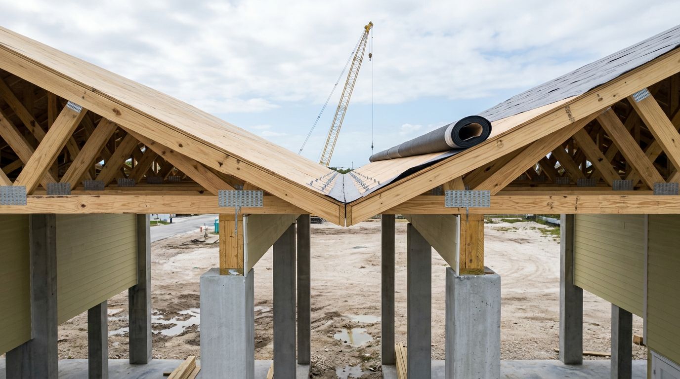
- Alignment along module marriage lines.
- Top elevations of caps, beams, or pads.
- Width and length of bearing surfaces.
- Placement of anchor rods, straps, plates, or embeds.
The structural engineer's drawings control the required dimensions and tolerances. Installation crews should not move a bearing point or modify an embedded connection based on convenience.
Confirm flood-related elevation requirements
In Florida coastal areas, the finished-floor elevation and lowest structural elements may be governed by floodplain rules and the project's approved documents. The surveyor's elevation reference ties the foundation to that required height.
This work also helps identify changes caused by settlement, form movement, or concrete finishing. Even a small difference between supports can matter when long modular sections must bear evenly.
Accurate layout supports a safer modular construction installation process because the crane crew and setting team can arrive to verified bearing locations rather than unresolved field questions.
The Instruments and Records That Support Accuracy
Surveyors choose instruments based on the site, the required precision, and available control. A robotic total station is often well suited to foundation layout because it measures angles, distances, and elevations from known control points.
GNSS equipment can help establish broader site control in open areas. However, it may be less useful near tree cover, tall structures, or locations where satellite reception is blocked. For close foundation work, a total station and level remain common tools.
Total stations check position and height
With a total station, the surveyor can stake a column center, measure the corner of a form, or shoot the top of a concrete cap. The instrument compares the measured point with its planned coordinate.
That comparison shows both direction and distance of any discrepancy. Instead of guessing that a support is "close enough," the crew receives a measurable correction.
A level and grade rod provide another dependable method for checking elevations. On projects with many elevated supports, crews often take repeated shots as concrete work progresses.
As-built documentation closes the loop
An as-built survey records the location and elevation of completed work. It may document foundation corners, columns, piers, grade beams, slab edges, and other elements named in the contract or permit requirements.
The record gives the owner, contractor, engineer, and installation team a common reference. It can also identify an issue while correction is still practical.
For modular home setup, a useful field package often includes marked plans, control-point information, elevation notes, and a clear report of any item that differs from the drawings. Good records reduce misunderstandings when several trades work on site at different times.
Field Checks Before Modular Home Installation
The final verification should happen before delivery trucks and cranes commit to the site. Once modules are staged nearby, a misplaced support can affect the entire day's schedule.
A pre-set walk should include the surveyor when the project is complex, elevated, or has a tight tolerance between the module frame and foundation supports. The installer, site superintendent, concrete contractor, and crane coordinator should also understand the verified layout.
Compare the foundation to the module support plan
The team should compare the completed foundation against the module support plan, including marriage-line supports and any concentrated loads. They also confirm access around the foundation for rigging, equipment, and crew movement.
This is the point to resolve questions about bearing pads, anchor hardware, shims, or connection details. Any field change that affects structural support needs review by the design professional responsible for the plans.
A final foundation check should never rely on a promise that an issue "will probably work." The crane lift is not the time to discover that a support line misses the module frame.
Access conditions can affect the verification plan
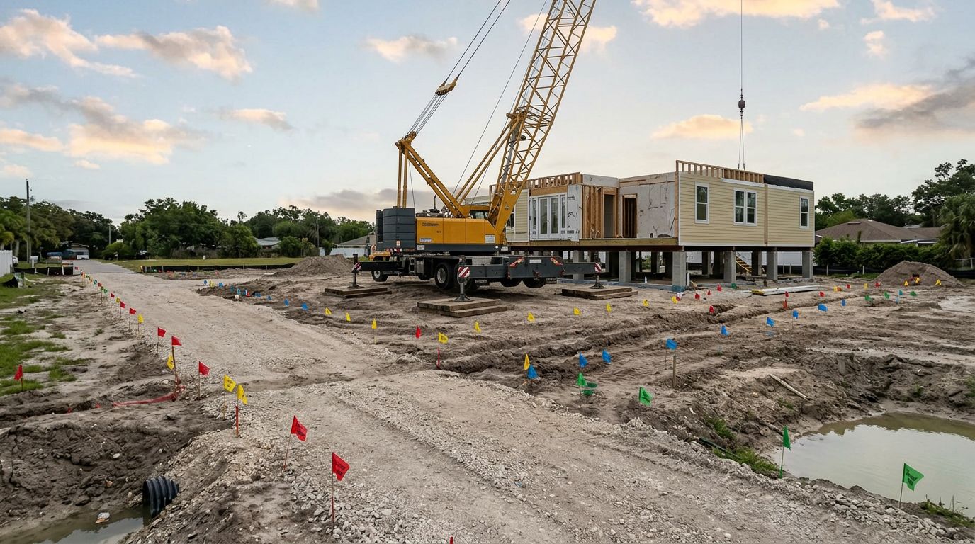
Survey accuracy and lift planning connect on difficult sites. The crane route, delivery path, turning radius, overhead lines, tree limbs, gates, drainage swales, and soft shoulders can affect where equipment can safely stand.
Crane outriggers place heavy point loads on the ground. Soft soil or recently placed fill may require mats or ground improvement before the crane arrives. A narrow waterfront lot may also require off-site staging, temporary traffic control, or a smaller crane.
Weather matters as well. Wind limits come from the crane's operating requirements and the lift plan. Rain can soften access routes, obscure layout marks, or delay concrete-related corrections.
Clear communication prevents standby charges and repeat mobilization. The delivery carrier, crane company, installation crew, and site lead need one confirmed schedule.
What Happens When Measurements Do Not Match
A discrepancy does not always mean the project has failed. It does mean work should pause long enough to measure the condition, identify the cause, and obtain direction from the right party.
The surveyor documents the actual position or elevation. Then the contractor compares it with the approved drawings and required tolerance. If the condition affects structural bearing, connections, or flood elevation, the engineer or architect must review the correction.
Corrections need written direction
Possible corrections may include modifying a concrete cap, adding an engineered bearing detail, adjusting approved connection hardware, or rebuilding an element that sits outside tolerance. The proper fix depends on the plans and the measured condition.
Crews should not solve a support issue by adding random blocking, cutting structural components, or shifting the module away from its planned location. Those actions can create new load-path problems.
Written direction also protects the project schedule. It tells the installation crew when the foundation is ready and identifies who is responsible for completing the correction before a new set date.
Final Thoughts
Accurate modular foundation setout starts long before the crane arrives. Survey control, centerline layout, elevation checks, and as-built records give every trade the same dependable reference.
For elevated coastal work, verified bearing points matter as much as the overall building footprint. When the foundation matches the approved plans, modular installation can proceed with fewer surprises, safer lifting conditions, and a structure that bears where it was designed to bear.
Recent Posts